Good day All,
Welcome back!!!
As part of some IP change we did IP changes for C7000 frame and below are the steps we followed....


b. Connect to the Server to which new ILO IP is not pinging using command

c. Most cases the new IP can be force applied by simply putting it into DHCP and then reverting (turning off the DHCP option. Insert the following commands one by one after step B.


Hope this helps someone!!!! and i got to pass on special thanks to Prasanth my buddy for capturing the screenshot and document it..
Until next one you all have a good day!!!!
Welcome back!!!
As part of some IP change we did IP changes for C7000 frame and below are the steps we followed....
Changing the IP address.
1.
Login to the Virtual Connect
Manager assigned to the enclosure being worked on.
2.
Click on the ‘IP Address’ link under section Domain Settings
3. Uncheck the box ‘Use Virtual Connect Domain IPv4 Address’ Click Apply. Do not proceed without doing this. It’s very important.
3. Uncheck the box ‘Use Virtual Connect Domain IPv4 Address’ Click Apply. Do not proceed without doing this. It’s very important.
Note: Now if you ping VC ip that will not work.

4.
Login to the Active OA
(On-Board Administrator) module for the schedule c7000 or c3000 enclosure to be
changed.
5.
Click on the IPv4 link under the Enclosure Bay IP Addressing
section. Click on the ‘Device Bays’ tab. Change the IP address for
each slot along with the subnet mask and gateway. New IP is in column G
of the excel sheet. Following remains same for all ILO/VC and OA
a.
Subnet Mask: x.x.x.x
b.
Gateway: x.x.x.x
c. DNS: x.x.x, x.x.x.
6.
Make sure that you check the enabled box rounded in red below,
across each of the box where you are updating the IP/MASk/Gateway

7.
Click on the ‘Apply’ button towards the bottom of the screen to
save the changes.
8.
Once applied validate the current
address field boxed in yellow above is updated with the new IP address. It
may take some time to update.
9.
Click on the ‘Interconnect Bays’ tab and change/add the assigned IP for each slot with New IP Following remains same for all ILO/VC and OA
a.
Subnet Mask: x.x.x.x
b.
Gateway: x.x.x.
c. DNS: x.x.x.x, x.x.x.
10. Check the enabled box.
11. There is no change in the
NTP server IP.

12. Click on the ‘Apply’
button towards the bottom of the screen to save the changes.
13. The IP should be updated in
the “current address” for the first two rows. It may not update for the
remaining two rows, which are for CISCO Switches for SAN. Those two needs
configuration change at switch end also.
So, if minimum two rows (mostly top most two rows) should be
updated.
14. Next go to “Enclosure
Settings” and click on the Enclosure TCP/IP Settings link.
15.
Uncheck the box ‘Enclosure IP Mode’ and click apply. – Very important. Do not proceed without completing
this step, else you may lose connectivity to OA and onsite support may be
needed.

16. When enclosure IP mode is
selected both primary and secondary OA are accessible using the IP of the
active or OA1, dynamically switching between the OA at the back ground when
failover happens. Our purpose here is to access both OAs with their individual
IPs during failover/fail back. Do the following to test the same after step 15.
a. Login to the stand by OA.
You will see nothing in that screen except an option for failover.
b. Do the active to stand by failover.
c. Now you would be logged
out and you should be able to log into the active OA using the IP of the
previous stand by OA.
d. Once this verified proceed
to next step.
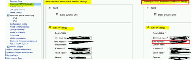
17. Log into active OA. Under
the static IP Setting section change the first IP address, subnet mask, gateway
of Standby OA to
the new assign IP then click apply.
***IMPORTANT*** DO NOT change the IP for active OA until you have validated you
have connectivity for passive OA.
Note: Standby OA will be
always at the right hand side (even after a failover) as underlined in red
below.

18. Verify that new IPs are
applied to the OA. Log into active OA through putty and type in the below command
and verify that stand by OA IP/Mask/Gateway is applied.
Show OA network standby

Once OA IP is changed, get in touch with Hawley, Jeremy of network
team to update the VLAN at switch side for the OA you have worked. Provide him
the MAC address of the stand by OA shown below

19. Once standby OA is flipped
to the new VLAN by network team, try pinging the stand by OA. If pinging log
into the new IP of the stand by OA; and then switch it into an active OA. Now
change the IP of the second OA, which is now standby. (Repeat of steps 30 and
31). Make sure you give the MAC of the next/remaining OA IP to Network team
now.
20. Once network team
completed the VLAN change for the second OA also, make sure that you can ping
and log in to the new OA (which is standby now) using the new IP.
21. Validate that you can ping
the new ILO IPs and Interconnect bay IPs updated in step 19 – 26.
22. If we cannot ping any of
the ILO IPs do the following
a. Log into the active OA
through putty

b. Connect to the Server to which new ILO IP is not pinging using command
connect server <bay number of the server>

c. Most cases the new IP can be force applied by simply putting it into DHCP and then reverting (turning off the DHCP option. Insert the following commands one by one after step B.
set
/map1/dhcpendpt1 EnabledState=yes
set /map1/dhcpendpt1
EnabledState=no
If the new IP is applied and pinging then you
can skip steps d, e and f below. Else proceed to step d.
d. Verify the IPs / mask and
gate way assigned to the ILO of the server. Below commands will help you to
identify the IP/Mask and gateway assigned to the server.
Log into the active OA using putty
connect server <bay number of the server>
-
Connects to the server
where ILO IP need to be verified.
show
/map1/enetport1/lanendpt1/ipendpt1 -
Shows
IP & mask applied to the ILO of server highlighted in yellow above
show
/map1/gateway1
Shows
the gateway applied to the ILO server highlighted in yellow above
e. If any of the assigned
value is not as per the new IP/mask/gateway then you can use the below commands
to key in the same. Before running the command ‘connect’ to the server as in
step highlighted in yellow above
set
/map1/enetport1/lanendpt1/ipendpt1 SubnetMask=x.x.x.x
set
/map1/enetport1/lanendpt1/ipendpt1 IPv4Address=<your
IP address goes here>
set
/map1/gateway1
AccessInfo=x.x.x.x
f. Repeat the step C and
confirm that correct values are applied.
23. If we cannot ping the
interconnect IPs do the following
a. Connect to the active OA
through putty
b. Verify the IPs / mask and
gate way assigned to the inter connect bay of the server using the below
command (only first two values are of important)
show
EBIPA interconnect
c. If the new IP, Mask or gateway
is not applied use the below commands to set the same.
set ebipa interconnect
x.x.x.x x.x.x.x 1 (Applies IP and mask for bay 1)
set ebipa interconnect
gateway x.x.x.x 1 (Applies gateway for bay 1)
Repeat the above step for interconnect bay 2
as well.
d. Repeat step B and make
sure that new IP/mask/gateway are applied to first two interconnect bay.
e. If inter connect bay is
still not ping-able get in touch with network team to test the firewall
settings.
24. Once both OAs has been
assigned IPs ‘check the box ‘Enclosure IP Mode’ and click Apply
(Reversal of what is done in step 14 & 15)
25. Login to the first virtual
connect module IP that has the newly assigned IP located in interconnect bay 1
in order to login to the Virtual Connect Manager.
New IP Assigned at Step 9
26. Once in the Virtual
Connect Manager click on the ‘IP Address’ link under the Domain Settings
section. Click the box ‘Use Virtual Connect Domain IPv4 Address’
(Reversal of what is done in step 3)
27. Enter the newly assigned
IP address, subnet mask and gateway for the Virtual Connect Domain name. New
IP is therein column G, against Virtual Connect Mgr. Mask/Gateway remains the
same.
28. Click Apply.

29.
Click the ‘Configuration’ link under the Domain Settings
section.
30.
Type in the new Virtual Connect Domain Name in the ‘Name of the
Virtual Connect Domain Name:’ field. Just type in the NETBIOS name alone
excluding domain name.

31.
Click Apply
ILO Configuration
32. List out all the blades on
the enclosure.
33. Log into the ILO of each
of the server.
34. Go to Network èILO Dedicated network port
è IPv4 Tab
35. Uncheck “enable DHCPV4”
36. Check “enable DNS server
registration”
37. Click submit. And it will
prompt for ILO rest, do not reset now.

38. Next click on the IPv6 tab
39. Uncheck all the boxes.

40. Click Submit. It will save
the configuration. Do not rest the ILO yet.
41. Next go to the general tab. Update the hostname and
domain name. Details that need to go into these fields is given in the excel
sheet in column H across each server name.
42. Once done click on submit
button. It will give a warning to Rest the ILO. Rest the ILO now by clicking
button marked in red.

Kindly
note that the above steps needs to be done for each of the ILOs of each individual
blades on the frame that you are going to work.
Until next one you all have a good day!!!!
Nice one Naveen.. ����
ReplyDeleteNice one Naveen.. ����
ReplyDeleteVery useful for admins ... thanks Naveen... looking more useful articles like this...
ReplyDeleteSuper Naveen
ReplyDelete