Sunday, May 29, 2016

IP Changing on C7000 for ILO/OA/VC

Good day All,

Welcome back!!!
As part of some IP change we did IP changes for C7000 frame and below are the steps we followed....


Changing the IP address.
1.     Login to the Virtual Connect Manager assigned to the enclosure being worked on.
2.     Click on the ‘IP Address’ link under section Domain Settings
3.     Uncheck the box ‘Use Virtual Connect Domain IPv4 Address’ Click Apply. Do not proceed without doing this. It’s very important.
Note: Now if you ping VC ip that will not work.


4.     Login to the Active OA (On-Board Administrator) module for the schedule c7000 or c3000 enclosure to be changed.

5.     Click on the IPv4 link under the Enclosure Bay IP Addressing section.  Click on the ‘Device Bays’ tab.  Change the IP address for each slot along with the subnet mask and gateway.  New IP is in column G of the excel sheet. Following remains same for all ILO/VC and OA
a.      Subnet Mask: x.x.x.x
b.      Gateway: x.x.x.x
c.      DNS: x.x.x, x.x.x.

6.     Make sure that you check the enabled box rounded in red below, across each of the box where you are updating the IP/MASk/Gateway


7.     Click on the ‘Apply’ button towards the bottom of the screen to save the changes.

8.     Once applied validate the current address field boxed in yellow above is updated with the new IP address. It may take some time to update.

9.     Click on the ‘Interconnect Bays’ tab and change/add the assigned IP for each slot with New IP  Following remains same for all ILO/VC and OA
a.      Subnet Mask: x.x.x.x
b.      Gateway: x.x.x.
c.      DNS: x.x.x.x, x.x.x.

10.  Check the enabled box.
11.  There is no change in the NTP server IP.


12.  Click on the ‘Apply’ button towards the bottom of the screen to save the changes.

13.  The IP should be updated in the “current address” for the first two rows. It may not update for the remaining two rows, which are for CISCO Switches for SAN. Those two needs configuration change at switch end also.
So, if minimum two rows (mostly top most two rows) should be updated.

14.  Next go to “Enclosure Settings” and click on the Enclosure TCP/IP Settings link.
15.   Uncheck the box ‘Enclosure IP Mode’ and click apply. – Very important. Do not proceed without completing this step, else you may lose connectivity to OA and onsite support may be needed.


16.  When enclosure IP mode is selected both primary and secondary OA are accessible using the IP of the active or OA1, dynamically switching between the OA at the back ground when failover happens. Our purpose here is to access both OAs with their individual IPs during failover/fail back. Do the following to test the same after step 15.
a.     Login to the stand by OA. You will see nothing in that screen except an option for failover.
b.     Do the active to stand by failover.
c.      Now you would be logged out and you should be able to log into the active OA using the IP of the previous stand by OA.
d.     Once this verified proceed to next step.

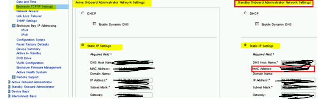
17.  Log into active OA. Under the static IP Setting section change the first IP address, subnet mask, gateway of Standby OA to the new assign IP then click apply
***IMPORTANT***  DO NOT change the IP for active OA until you have validated you have connectivity for passive OA.

Note: Standby OA will be always at the right hand side (even after a failover) as underlined in red below.


18.  Verify that new IPs are applied to the OA. Log into active OA through putty and type in the below command and verify that stand by OA IP/Mask/Gateway is applied.

Show OA network standby


Once OA IP is changed, get in touch with Hawley, Jeremy of network team to update the VLAN at switch side for the OA you have worked. Provide him the MAC address of the stand by OA shown below


19.  Once standby OA is flipped to the new VLAN by network team, try pinging the stand by OA. If pinging log into the new IP of the stand by OA; and then switch it into an active OA. Now change the IP of the second OA, which is now standby. (Repeat of steps 30 and 31). Make sure you give the MAC of the next/remaining OA IP to Network team now.

20.  Once network team completed the VLAN change for the second OA also, make sure that you can ping and log in to the new OA (which is standby now) using the new IP.

21.  Validate that you can ping the new ILO IPs and Interconnect bay IPs updated in step 19 – 26.

22.  If we cannot ping any of the ILO IPs do the following
a.     Log into the active OA through putty


b.     Connect to the Server to which new ILO IP is not pinging using command
connect server <bay number of the server>


c.      Most cases the new IP can be force applied by simply putting it into DHCP and then reverting (turning off the DHCP option. Insert the following commands one by one after step B.

set /map1/dhcpendpt1 EnabledState=yes
set /map1/dhcpendpt1 EnabledState=no

If the new IP is applied and pinging then you can skip steps d, e and f below. Else proceed to step d.

d.     Verify the IPs / mask and gate way assigned to the ILO of the server. Below commands will help you to identify the IP/Mask and gateway assigned to the server.

Log into the active OA using putty

connect server <bay number of the server> -
Connects to the server where ILO IP need to be verified.

show /map1/enetport1/lanendpt1/ipendpt1  -
Shows IP & mask applied to the ILO of server highlighted in yellow above

show /map1/gateway1                                       
Shows the gateway applied to the ILO server highlighted in yellow above

e.     If any of the assigned value is not as per the new IP/mask/gateway then you can use the below commands to key in the same. Before running the command ‘connect’ to the server as in step highlighted in yellow above

set /map1/enetport1/lanendpt1/ipendpt1 SubnetMask=x.x.x.x
set /map1/enetport1/lanendpt1/ipendpt1 IPv4Address=<your IP address goes here>
set /map1/gateway1 AccessInfo=x.x.x.x

f.       Repeat the step C and confirm that correct values are applied.

23.  If we cannot ping the interconnect IPs do the following
a.     Connect to the active OA through putty
b.     Verify the IPs / mask and gate way assigned to the inter connect bay of the server using the below command (only first two values are of important)

show EBIPA interconnect


c.      If the new IP, Mask or gateway is not applied use the below commands to set the same.

set ebipa interconnect x.x.x.x x.x.x.x 1     (Applies IP and mask for bay 1)
set ebipa interconnect gateway x.x.x.x 1      (Applies gateway for bay 1)

Repeat the above step for interconnect bay 2 as well.

d.     Repeat step B and make sure that new IP/mask/gateway are applied to first two interconnect bay.
e.     If inter connect bay is still not ping-able get in touch with network team to test the firewall settings.

24.  Once both OAs has been assigned IPs ‘check the box ‘Enclosure IP Mode’ and click Apply
(Reversal of what is done in step 14 & 15)

25.  Login to the first virtual connect module IP that has the newly assigned IP located in interconnect bay 1 in order to login to the Virtual Connect Manager.
New IP Assigned at Step 9

26.  Once in the Virtual Connect Manager click on the ‘IP Address’ link under the Domain Settings section.  Click the box ‘Use Virtual Connect Domain IPv4 Address’ 
(Reversal of what is done in step 3)

27.  Enter the newly assigned IP address, subnet mask and gateway for the Virtual Connect Domain name.  New IP is therein column G, against Virtual Connect Mgr. Mask/Gateway remains the same.

28.  Click Apply.


29.   Click the ‘Configuration’ link under the Domain Settings section.
30.   Type in the new Virtual Connect Domain Name in the ‘Name of the Virtual Connect Domain Name:’ field. Just type in the NETBIOS name alone excluding domain name.


31.   Click Apply

ILO Configuration
32.  List out all the blades on the enclosure.
33.  Log into the ILO of each of the server.
34.  Go to Network èILO Dedicated network port è IPv4 Tab
35.  Uncheck “enable DHCPV4”
36.  Check “enable DNS server registration”
37.  Click submit. And it will prompt for ILO rest, do not reset now.


38.  Next click on the IPv6 tab
39.  Uncheck all the boxes.


40.  Click Submit. It will save the configuration. Do not rest the ILO yet.

41.  Next go to the general tab. Update the hostname and domain name. Details that need to go into these fields is given in the excel sheet in column H across each server name.
42.  Once done click on submit button. It will give a warning to Rest the ILO. Rest the ILO now by clicking button marked in red.


Kindly note that the above steps needs to be done for each of the ILOs of each individual blades on the frame that you are going to work.


Hope this helps someone!!!! and i got to pass on special thanks to Prasanth my buddy for capturing the screenshot and document it..
Until next one you all have a good day!!!!


Monday, May 16, 2016

How do you know if you need to increase Page File

Good day All,

Welcome back!!! Its holiday time for my daughter so she kept me busy for last 3-4 weeks so never got time to post anything.

The other day i was troubleshooting a Server performance issue and noticed that Server was reporting running out of page file/Virtual memory, so thought to share with you all where you can find this warning  in Windows 2008/2012.

Under Event Log:


How much to increase is a big question right? well you all always start with going to Page file settings and see what Microsoft recommends , but if you want to become a good Windows Admin then i highly recommend reading this article by the famous guy called

Mark Russinovich - https://blogs.technet.microsoft.com/markrussinovich/2008/11/17/pushing-the-limits-of-windows-virtual-memory/

So after reading this article i guess if anyone ask you how much should i set the page file, i guess below should your answer

To optimally size your paging file you should start all the applications you run at the same time, load typical data sets, and then note the commit charge peak (or look at this value after a period of time where you know maximum load was attained). Set the paging file minimum to be that value minus the amount of RAM in your system (if the value is negative, pick a minimum size to permit the kind of crash dump you are configured for). If you want to have some breathing room for potentially large commit demands, set the maximum to double that number.

Hopefully this helps someone and until the next one you all have a good day!!!!

Saturday, April 9, 2016

Generating Full,kernel dump from VMware Virtual Machines

Good day All,

Welcome back!!!

Lately we started to see lot of VM's going down and when we reach out to VMware they analyze and as usual asking us to go to Microsoft other than VMware issue.

Lot of the Virtual machines when they hung manual hard reboot is required.During the hung if you try to use keyboard to generate dump so far i was never successful and end up hard reboot the Server with no dump .

So for all these problems now we have tool call VMSS2CORE, this tool is internally used by VMware, now its available for download, click here

 Well wondering what this tool will do for you, if you go over link it explains in brief for starters .. lets assume  VM is hung so during the outage take a snapshot of the VM  and then reboot the VM.
After you took the snapshot go and browse datastore for the snapshot file and you will see a file with .vmsn as below..


download the .vmsn file and place it in the same directory where you downloaded and kept vms2core-win.exe


Now all you have to do the vmss2core command as below

Full memory dump for Windows 2003\2008 VM:
vmss2core-win -W filename.vmsn

Kernel dump for Windows 2003\2008 VM:
vmss2core-win -WK filename.vmsn


Full memory dump for Windows 2012 VM:

vmss2core-win -W8 filename.vmsn

Note:
I tested the tool on windows 2003\2008\2012.. WK which is to create Kernel dump works for Windows 2003/2008 but didn't work for Windows 2012.

If you go over the tools description it will tell you that you can create dump by suspending the VM and downloading the .VMSS file.

this is my take on taking the dump using the suspend state

Advantage:
Suspend state File size will be smaller when compared to Snapshot File size will be very helpful for larger Virtual Machines.

Dis-advantage:
You will be in outage when the Server hung, so putting in suspend mode and then wait till you download to local disk will consume lot of time which will add to your overall downtime window.
So if downtime is not a issue then try suspend state.


this helped me and hopefully this will someone, till next one hope you all have a good day!!!

Esxi host - Pause Flood Protection - VM's locked.

Good day All,
Welcome back!!!

Today will go over a issue we had couple of days ago on a Esxi host. Just to give a brief on our environment we have a HP C7000 Frame and 6 blades are running Esxi covering about 100 odd Virtual machines. So out of the 6 blade we had about 15 VM's running on a Esxi host and the host went to isolation mode.

During the outage we logged in to ILO and try to reboot the ESXi host to see if this kicks start's the HA feature but no luck as any traffic from the blade was completely blocked or stopped.

As we started to run out of time we went for work ground to fix the issue as during the outage we couldn't identify the root cause.
So following are the steps we performed

1. Disconnected the failed ESXi
2.Took a list of all VM's
3.Power down all the VM's
4. Removed the whole ESXi from cluster and from inventory
5.Browsed the datastore for each VM, add them to inventory and powered on
6, During the boot we choose the option "i moved it"

Note sure when Esxi host was hard rebooted why Datastore heart-beating didn't kick start HA and move the VM's that still we are investigating.

Hope this helps someone and until next one you all have a good day!!!


Thursday, March 24, 2016

NFS Storage for ESXi5.5

Good day All,

Welcome back!!!

In-case your are not a big fan of iscsi target Server but want to use NFS for shared storage to create a ESXi cluster here are the below steps which i followed and worked for me...


1. We need to add the Feature if already File Server role is enabled, if not then enable Server for NFS under File and Storage Service ,File and iSCSI Services as below


2.  Create a Folder which you want to be shared on the Esxi host..in my example i created as NFS_Mount.
Right click got to Properties and click on NFS Sharing tab and click Manage NFS Sharing


Change the permission from Read only to Read-Write and click allow Root access if you need to login as root and configure the storage on ESXi host as below


Click ok apply it and close the properties window.

3. Login to Esxi using the vSphere client , go to Configuration and click Storage.
Under storage click Add Storage


Select NFS


Provide a target Server where NFS share is created, give the folder name you have used and datastore name and click Next


Review everything and click Finish


So you have successfully add the NFS share ..


you can do the same for the other ESXi host and use it in your LAB incase you ever have to build a ESXi cluster.


Hope this helps someone and until next one you all have a good day!!!

Windows 2012 R2 iSCSI Target Server for Esxi 5.5

Good day All,

Welcome back!!!
Its been a break couple of days lot of other work kept me busy in writing a post.
As i am still playing with my Nano Servers, thought to setup in Parallel a ESXi Cluster too so that i can test and play both in VMware and also Hyper V.

When it comes to storage earlier i used open filer a VM appliance which you can download and configure as iSCSI target Server as Windows based iSCSI Target Server never worked.

So with Windows 2012 R2 inbuilt ISCSI target i started to test the ESXi host to see if this recognizes  the Luns.

Note: If you see the below Lab details, i have used a dedicated iSCSI IP for communication.

Lab:


Domain Name: vlab

Domain Controller:

FOODC - 192.168.1.20 Windows 2012 R2
iSCSI IP: 192.168.2.20

ESX HOSTS:

FOOESX1: 192.168.1.81
iscsi IP: 192.168.2.81

FOOESX2: 192.168.1.82
iscsi IP: 192.168.2.82


Setting up iSCSI Target on Windows 2012 R2 i will not go over because i went in detail in my First post this year and you can check the link

Steps to be done on the ESXi Host:


1. install the vSphere Client
2. Connect the ESxi host
3.Click Configuration tab and make sure to update Time Configuration, DNS and Routing


4.Click on Network Adapters and make sure you have a dedicated NIC for iscsi traffic.
So if you see below i have added 1 more NIC for iscsi traffic called vmnic1


5. Go to Networking and click on Add networking as below


a. Select VMKernel and click next


b, Select a dedicated NIC for iscsi traffic and click Next


c. Keep the default or if you need to change the name from VMKernel you can do it and click next


d. Assign a IP Address for the NIC and click Next


e.Click next and finish and you have just created a VMKernel Port group and a dedicated switch for iscsi traffic
 

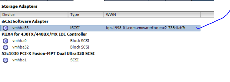
6. Now its time add the iscsi initiator , go to storage adapters and click Add


7. Ping the 2 Esxi host VMKernal IP from iscsi target server to make sure its pinging on the dedicated NIC


8. Now go to Windows 2012 R2 Server, create a iSCSI Virtual disk and add the 2 esxi host IP address..


9. Now in storage Adapters click Properties


on the Network configuration tab, add the vmkernel port group we created earlier.


Under Dynamic Discovery add the iscsi target Server IP and click ok


Now automatic rescan of adapter will happen or you do it manually by clicking Rescan All...
As seen below the new 90 GB Lun is attached and mounted to ESXi host.


9. Follow the same steps on the other ESXi host


Well this was easy.. hope this helps someone and until next one you all have a good day!!!!

Monday, February 29, 2016

Windows Boot Process

Good day All,
Welcome back!!!
I am not going to take credit for this screen shot just took it from Microsoft Virtual academy course, check it out if need to learn more.

Just putting them together so that we can have this handy when trying to troubleshoot a Windows boot issue to understand which part of the process may be failing..


Various process that gets loaded during the boot process:


If anyone really wants to learn more on each phase of boot process and also various memory Management terms best book to have handy is System Internals 2 Part series, excellent books to have it in your store.
Hope this helps someone, until next one you all have good day!!!